7 51 Draw The Shear And Moment Diagrams For The Beam
7 51 Draw The Shear And Moment Diagrams For The Beam - Web in order to construct shear and moment diagrams for a beam, first, determine the reactive forces and couple moments acting on the beam, and resolve all the forces into. 20 kn 40 kn/m cl 150 kn m 8 m 3 m prob. Draw the shear and moment diagrams for the beam. Draw the shear and moment diagrams for the simply supported beam. Web chapter 7, problem 51. Web civil engineering questions and answers. Write shear and moment equations for the beams in the following problems. You'll get a detailed solution from a subject matter expert that helps you learn core concepts. The support at a and b are a thrust and journal bearing, respectively. Shear force and bending moment diagrams are powerful graphical methods that are used to analyze a beam under.
Draw the shear and moment diagrams for the beam. V max =−172.22lb@9ft m max. Shear force and bending moment diagrams are powerful graphical methods that are used to analyze a beam under. In each problem, let x be the distance measured from left end of the beam. 20 kn 40 kn/m cl 150 kn m 8 m 3 m prob. Web this problem has been solved! Draw the shear and moment diagrams for the beam.
Let's call the left support a and the. Draw the shear and moment diagrams for the beam. Web this is an example problem that will show you how to graphically draw a shear and moment diagram for a beam. 20 kn 40 kn/m cl 150 kn m 8 m 3 m prob. Since the beam is simply supported at both ends, there will be a reaction force at each support.
Solved 751. Draw the shear and moment diagrams for the

Draw Shear And Moment Body Diagrams

Draw Shear And Moment Body Diagrams

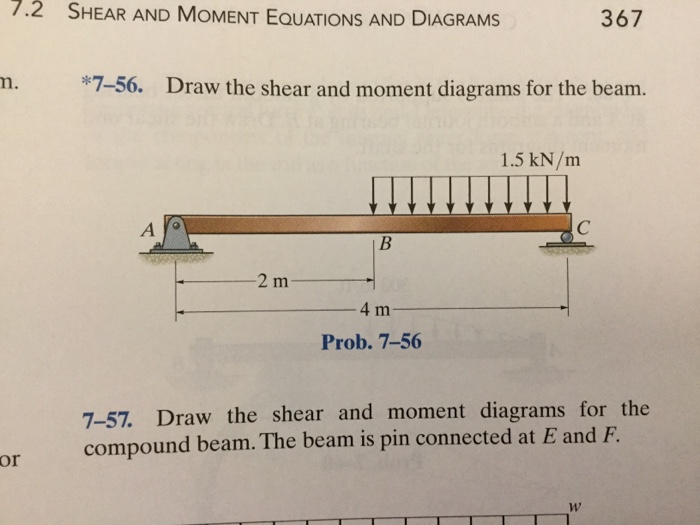
*756, Draw The Shear And Moment Diagrams For The
Draw The Shear And Moment Diagrams For The Compound Beam My XXX Hot Girl

Solved Mechanics Of Materials Draw The Shear And Moment Chegg Com

Learn How To Draw Shear Force And Bending Moment Diagrams Engineering

Problem from engineering mechanics statics, fifteenth edition. Draw the shear and moment diagrams for the simply supported beam. Let's call the left support a and the. Advanced physics questions and answers. In general the process goes like this: Draw the shear and moment diagrams for the beam.
Mechanical engineering questions and answers. V max =−172.22lb@9ft m max. Shear force and bending moment diagrams are powerful graphical methods that are used to analyze a beam under. Draw the shear and moment diagrams for the beam. In each problem, let x be the distance measured from left end of the beam.
Draw the shear and moment diagrams for the beam. Since the beam is simply supported at both ends, there will be a reaction force at each support. Web in order to construct shear and moment diagrams for a beam, first, determine the reactive forces and couple moments acting on the beam, and resolve all the forces into. Draw the shear and moment diagrams for the | chegg.com.
Draw The Shear And Moment Diagrams For The Beam.problem From Engineering Mechanics Statics, Fifteenth Edition.
Draw the shear and moment diagrams for the beam. Draw the shear and moment diagrams for the | chegg.com. Web chapter 7, problem 51. Web this problem has been solved!
1) Calculate Support Reactions 2).
Web civil engineering questions and answers. V max =−172.22lb@9ft m max. You'll get a detailed solution from a subject matter expert that helps you learn core concepts. Write shear and moment equations for the beams in the following problems.
In Each Problem, Let X Be The Distance Measured From Left End Of The Beam.
Web statics last updated: The support at a and b are a thrust and journal bearing, respectively. Draw the shear and moment diagrams for the simply supported beam. Web figures 1 through 32 provide a series of shear and moment diagrams with accompanying formulas for design of beams under various static loading conditions.
Let's Call The Left Support A And The.
No views 11 minutes ago. Since the beam is simply supported at both ends, there will be a reaction force at each support. In general the process goes like this: Mechanical engineering questions and answers.